
Cause Analysis and Treatment Measures of Centrifugal Compressor Failure
Release time:2026-09-16 Click:181
Cause Analysis and Treatment Measures of Centrifugal Compressor Failure? Centrifugal compressor occupies an irreplaceable position in chemical industry, coal chemical industry, air separation, various manufacturing processes, etc. Under the multiple effects of high speed, high pressure ratio and medium complexity, the failure of this kind of equipment has certain inevitability. Based on this, the systematic study of centrifugal compressor fault causes and corresponding treatment strategy, to ensure the equipment stable, long-term full and optimal operation has important practical significance.
Turbo-Tech introduced, centrifugal compressor failure analysis and treatment measures
1. Typical fault classification of centrifugal compressors
According to years of site, centrifugal compressor failures can be roughly summarized into the following categories:
Types of Failures Main Manifestations Hazard Degree
Abnormal vibration The vibration value of the shaft exceeds the standard and the vibration of the bearing housing is abnormally high
Bearing Damage Babbit Wear, Body Spalling, Shaft Hold High
Seal failure internal leakage, external leakage, oil-gas cross-channeling medium-high
Surge Phenomenon Periodic airflow backflow, extremely high roar
Decreased displacement, low pressure ratio, low efficiency
Abnormal temperature rise Bearing bush temperature, lubricating oil temperature, exhaust air temperature rise abnormally medium-high
2. In-depth analysis of the main failure causes of centrifugal compressors
(I) Abnormal vibration fault
1. Rotor unbalance
As the core component of the compressor, the balance accuracy of the rotor directly determines the operating status of the equipment. Common imbalance inducements include: impeller surface scaling or corrosion, balance disk wear, solid particles in the medium erosion of the impeller, interstage seal wear failure, etc. These factors will cause the rotor distribution to deviate from the design axis, resulting in periodic excitation forces.
2. Rotor misalignment
The alignment accuracy of the coupling is not up to standard, the uneven settlement of the unit foundation, and the stress of the pipeline will all cause misalignment between the rotors or between the rotor and the shaft system of the speed increase box. Slight misalignment will keep the vibration at a low level but accompanied by high bearing temperature, and serious misalignment will produce second-harmonic characteristic vibration.
3. Oil film whirl and oil film oscillation
When the rotor is running more than 1/2 of the first critical speed, if the viscosity of the lubricating oil is improperly selected, the clearance of the bearing bush is too large, or the temperature of the lubricating oil is improperly controlled, the journal is prone to instability and whirl in the oil film. When the vortex is close to the inherent rotor, it will evolve into a very strong oil film oscillation.
4. Airflow excitation
When the compressor operates at high pressure ratio and low flow rate, the interaction between the return flow area of the impeller outlet and the impeller channel will stimulate the inherent vibration near the blade. This kind of excitation force has nonlinear characteristics, and it is difficult to deal with it.
Bearing system failure
1. Journal bearing failure
-Babbit alloy layer shedding or cracking, mainly due to small bearing clearance, poor lubrication, foreign matter entering
-The wear of the bearing alloy exceeds the standard, which is mostly related to impurities in the oil and low oil pressure operation
-Bearing bush burning, common in cold start without comprehensive warm-up or instant oil cut-off
2. Thrust bearing failure
When the compressor operates under abnormal working conditions (such as surging), the axial force will fluctuate greatly or reverse. Wear of thrust disc and burning of thrust tile are common consequences.
3. Bearing failure
Failures such as fatigue pitting corrosion and frame fracture of bearings for speed-increasing boxes and auxiliary machines are mostly related to assembly technology, grease aging, and vibration and impact.
(III) Sealing system failure
1. Labyrinth seal failure
-Wear or broken sealing teeth
-Seal clearance abnormal due to rotor vibration or heat
-Steam or process gas back-flowing to the bearing box
2. Mechanical seal failure
-Wear of sealing surface of moving ring and static ring
-O-ring aging, spring failure
-Seal flushing system clogged or under pressure differential
3. Floating ring seals oil leaks
The clearance between floating ring and shaft sleeve is too small, lubricating oil pollution, oil-gas separator blockage will cause a large amount of sealing oil leakage.
(IV) Surge fault
Surge is one of the more dangerous faults of centrifugal compressors. Its essence is the low-frequency and high-amplitude air flow oscillation phenomenon that occurs in the unit and pipe network system when the compressor operates under the working condition of less than a small flow rate.
Predisposing factors:
-Sudden increase in the back pressure of the outlet pipe network (such as mistakenly closing the valve, anti-gasp valve failure)
-Inlet filter or cooler fouling leading to reduced flow
-The use lags behind when the gas consumption of the process system is large
-Improper setting of anti-surge control system parameters
Hazards: In a short period of time, it will cause serious damage such as sealing damage, bearing overheating, coupling twisting and so on.
(V) Performance degradation fault
1. Scale and corrosion of circulating parts
The impurities, water and acidic substances contained in the medium deposit or corrode in the impeller channel, inter-stage channel, volute and other parts, resulting in the reduction of the flow area and the roughness of the flow channel.
2. Increased sealing clearance between stages
Due to erosion or mechanical wear, the clearance of balance disk seal and labyrinth seal between stages exceeds the standard, resulting in an increase in inter-stage leakage and a decrease in volumetric efficiency.
3. Increased resistance of the suction filter system
Dust accumulation in the inlet filter and scaling in the cooler make the actual suction capacity lower than the design value.
Abnormal temperature rise
-Bearing bush temperature is too high: insufficient supply of lubricating oil, deteriorated oil quality, cooler failure
-Exhaust temperature is too high: aspiration temperature exceeds the standard, compression ratio is high, cooling water system failure
-Abnormal lubricating oil temperature: oil cooler scaling, insufficient cooling water flow, fuel tank heater failure
3. Targeted treatment measures
Vibration fault handling
1. Rotor unbalance treatment
-Implement online or offline dynamic balance correction
-Thoroughly clean the impeller channel for scaling
-Check and replace damaged balancing discs and balancing drums
Repair or replace corroded or eroded impellers
2. Rotor misalignment treatment
Re-aligning cold and hot states
-Check the settlement of the unit foundation and reinforce it if necessary
-Optimize the flexible design of pipelines to remove additional stresses in piping systems
3. Treatment of oil film instability
-Bearing clearance to design value
-Choose viscous lubricants
-Optimize the lubricant temperature control system
-Adding dampers or tilting pad bearings if necessary
Bearing fault handling
1. Shut down immediately to replace damaged bearing bushes or bearings
2. Recalculate bearing bush clearance and angle
3. Overhaul the lubricating oil system: clean the oil circuit, replace the filter element, and verify the pressure regulating valve
4. Improve the assembly process to avoid deformation of the tile back caused by barbaric construction
(III) Sealing system treatment
1. Replace worn seal assembly, seal clearance
2. Overhaul the flushing, cooling and isolation fluid systems of mechanical seals
3. Check the oil and gas pressure difference and smooth oil return when the floating ring seal leaks oil
4. Recalculate sealing gas/sealing oil pressure grades
Surge fault handling
1. Emergency treatment: Open the anti-surge valve (or return valve) immediately, and the exit back pressure
2. Anti-surge control system optimization: re-adjust the PI parameters to ensure the rapid response of the anti-surge valve
3. Process use: Avoid the compressor from running under small flow conditions for a long time
4. Pipeline network system transformation: reasonably set up return pipelines and increase the capacity of gas storage tanks
5. Interlocking logic optimization: set surge warning, automatically open anti-surge valve
(V) Performance degradation treatment
1. Chemical cleaning or mechanical descaling of impeller, volute and inter-stage channel
2. Replace interstage seals with excessive wear and tear
3. Wash or replace inlet filters, coolers
4. If necessary, carry out maintainability modification or overall replacement of the rotor
(VI) Abnormal handling of temperature rise
1. Check the heat exchange effect of oil cooler and water cooler
2. Check the quality, pressure and flow of lubricating oil
3. Process medium inlet temperature
4. Optimize the operating condition point of the compressor to avoid overpressure ratio operation
The above is the introduction of "Centrifugal Compressor Fault Cause Analysis and Treatment Measures". Centrifugal compressor is a key equipment with high technical content in the process industry, and its failure manifestations are diverse and the causes are complex. Only by combining daily maintenance, condition monitoring, standardized use and precise maintenance of some machines can the incidence of failures be maximized and the service life of equipment be extended.
Hot products
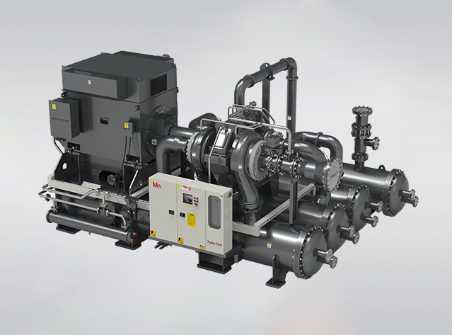
Mn (H) series centrifugal compressor
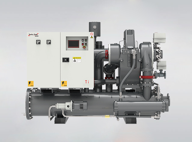
Ti series centrifugal air compressor
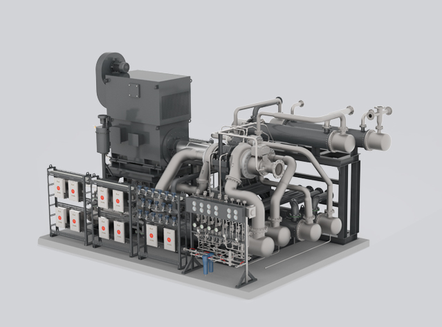
Ra series process gas compressors
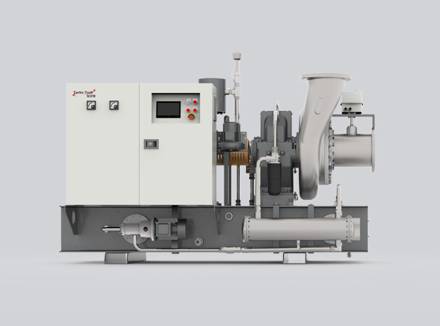
Ni series steam compressor
Tel:400-886-1856/+86 13395157738(Simon)
E-mail:sales@turbo-tech.cn / simonjin@turbo-tech.cn


