
Structure diagram of centrifugal compressor
Release time:2026-01-28 Click:72
Structure diagram of centrifugal compressor? As the core equipment of large-flow gas compression in modern industry, the stable operation of centrifugal compressor is inseparable from precise structural design. Although we can't show the picture directly, this paper will restore a "overall structure diagram of compressor equipment" in text form, and analyze its core composition, structural layout and functional synergy mechanism for you in detail.
Centrifugal compressor is mainly composed of two core parts: rotor (rotating part) and stator (fixed part). The whole machine usually adopts integral skid-mounted structure, which is convenient for assembly and maintenance.
First, the stator system
Stator is the "skeleton" and "channel" of compressor, which is responsible for fixing rotor and guiding gas flow.
1. Chassis
-Material: high-strength cast steel or alloy steel, with good rigidity and tightness.
-Structure: split horizontally, and the upper and lower halves are connected by bolts, which is convenient for maintenance.
-Function: Bearing all internal components, withstanding high pressure and preventing gas leakage.
2. Partition
-Installed in the casing to divide the compressor into multiple "stages".
-Including: air inlet partition, middle partition and exhaust partition.
-Function: It forms the gas passage between impellers at all levels and fixes the diffuser and guide elements.
3. Diffuser
-Located behind the impeller outlet of each stage.
-Structure: The circulation area gradually increases, which slows down the high-speed gas and converts kinetic energy into pressure energy.
-Type: smooth type, vane type and step type, which affect efficiency and stability.
4. Bend and Reflux
-Bend: Connect the diffuser and the backflow device to change the airflow direction.
-Reflux device: Built-in guide vanes can guide the airflow into the inlet of the next stage impeller evenly to reduce the eddy current loss.
5. Intake/exhaust pipe
-Air inlet: usually located at the low pressure end and connected to the filtration system.
-Exhaust port: located at the last stage, connected with cooler or pipe network.
Second, the rotor system
Rotor is the "heart" of compressor, which is responsible for converting mechanical energy into gas pressure energy.
1. Spindle
High-strength alloy steel is forged and quenched and tempered to ensure rigidity and fatigue resistance.
-Support mode: both ends are supported by radial bearings, and the axial direction is positioned by thrust bearings.
2. Impeller
-Core working parts, usually closed or semi-open structure.
-Blade back bending design to optimize aerodynamic performance.
-Installation method: heat sleeve on the spindle, key connection to transmit torque.
-Function: Drive gas to move when rotating at high speed, and improve gas speed and pressure under the action of centrifugal force.
3. Balance plate
-Installed at the high pressure end, and forced in the opposite direction to the impeller.
-Principle: Use the pressure difference between the high pressure area and the low pressure area to generate reverse axial force and balance the axial thrust generated by the impeller.
4. Shaft seal system
-Labyrinth seal: it is commonly used, and the throttle channel is formed by the tiny gap between the sealing teeth and the shaft to realize non-contact seal.
-Floating ring seal: used for high-pressure or toxic gases, and sealed by oil film.
-Dry gas seal/steam blocking seal: used in special working conditions to prevent medium leakage.
3. Bearing system: supporting rotation and ensuring stable operation.
1. Radial bearing
-Function: Support rotor weight and bear radial load.
-Type: Multi-wedge tilting pad bearing, self-adaptive centering, good vibration reduction performance.
2. Thrust bearing
-Installed at the non-driven end to bear residual axial force.
-Structure: Double-sided thrust block, including main and auxiliary thrust discs.
-Main thrust disc: it bears the residual axial force during normal operation.
-Auxiliary thrust disc: to prevent reverse movement during start-up and protect the rotor.
Four, the workflow diagram (combined with the dynamic understanding of the structure diagram)
1. Inhalation stage: air enters the core of the primary impeller from the air inlet pipe.
2. Acceleration stage: the impeller rotates at high speed, the gas is thrown to the edge, and the speed and pressure rise.
3. Diffuser stage: When high-speed gas enters the diffuser, the flow rate decreases and the pressure further increases.
4. Diversion stage: guided by a bend and a backflow device, uniformly entering the next stage impeller.
5. Multi-stage compression: repeat the above process and increase the pressure step by step until the target pressure is reached.
6. Exhaust stage: the final gas is collected by the volute and output by the exhaust pipe.
The structural diagram of centrifugal compressor is an important carrier to understand the working principle and maintenance points of equipment. Through the systematic analysis of the structural diagram, the functional orientation and operation logic of each component can be clearly defined, which provides theoretical support for the use, maintenance and optimization of equipment in industrial production.
Hot products
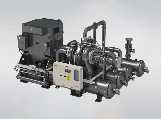
Mn (H) series centrifugal compressor
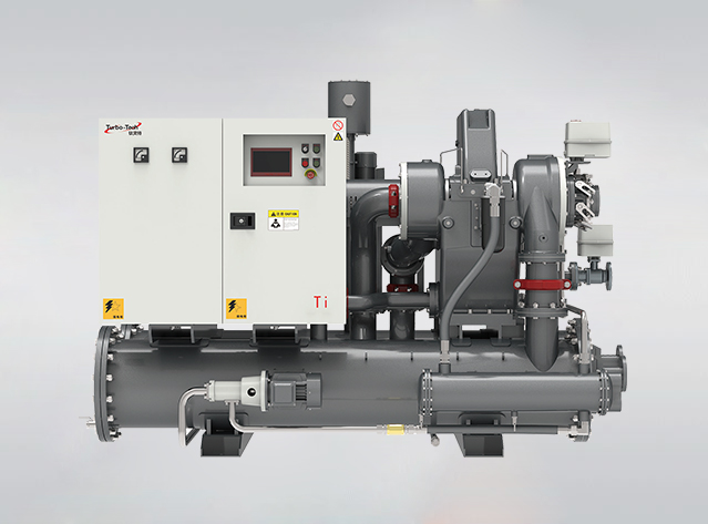
Ti series centrifugal air compressor
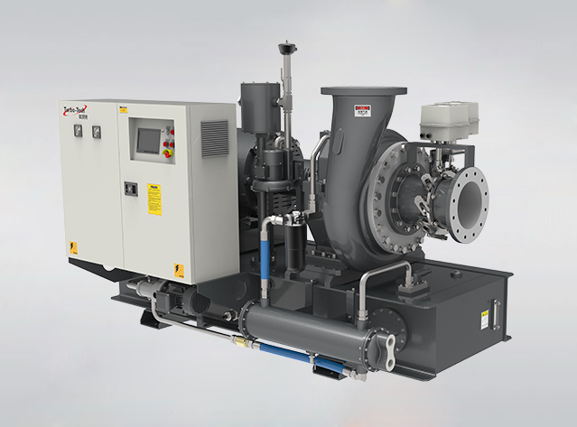
CF single stage high-speed centrifugal fan
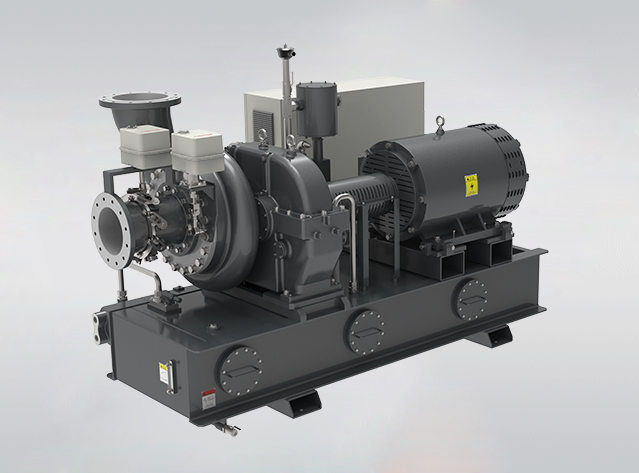
RF process fan and circulating fan
Tel:400-886-1856/+86 13395157738(Simon)
E-mail:sales@turbo-tech.cn / simonjin@turbo-tech.cn
CONTACT US


